VILLA / BEHSA PAYDAR MANA / STRUCTURAL DESIGN
From architectural form
to reinforcement detail.
A closer look at the reinforced concrete villa I worked on at Behsa Paydar Mana: its framing layout, connected foundations, column reinforcement, and beam detailing.
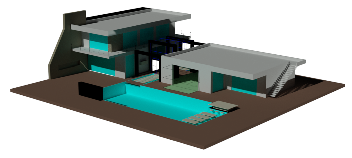
My contribution
Structural design and detailing during my work at Behsa Paydar Mana. This selection shows how the framing scheme is developed into reinforcement plans, member elevations, and cross-sections.
Framing plan ↓Foundations ↓Columns ↓Beams ↓
12 drawing sheets · Expand a drawing to inspect it, or open its full-resolution image.
01 / THE STRUCTURAL SCHEME
A plan that connects the details.
DRAWING 01 / st9.pdf
Framing plan and member references
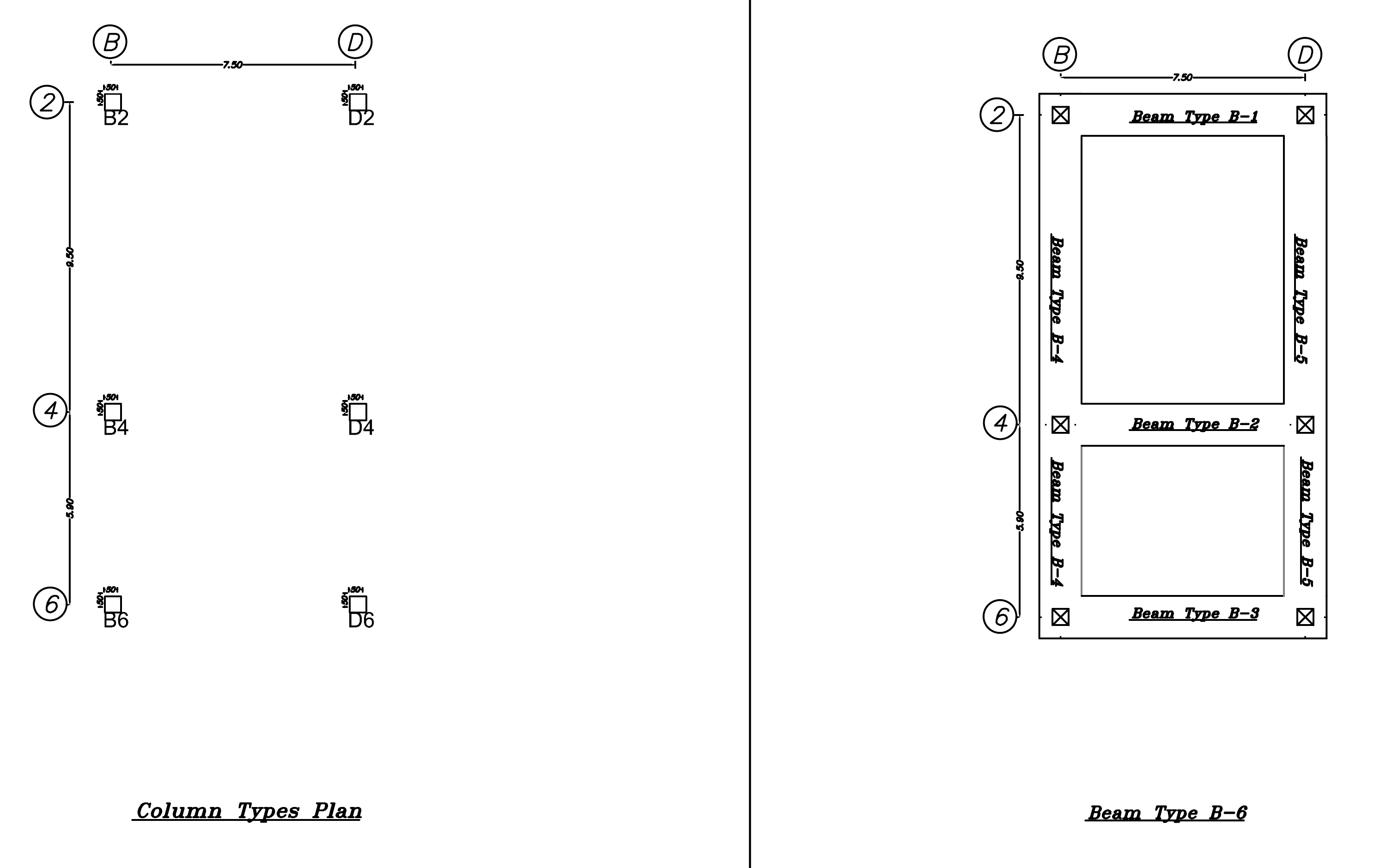
The column-type plan and beam layout establish how the drawing package fits together. Grid references locate the columns, while beam types B-1 through B-5 connect the framing plan to the reinforcement elevations. This coordination makes each member traceable from its position in the building to its detailed drawing.
Grid references · Column identification · Beam-type coordination
View drawing +
02 / FOUNDATIONS
Reinforcement from plan to section.
DRAWING 02 / 11.pdf
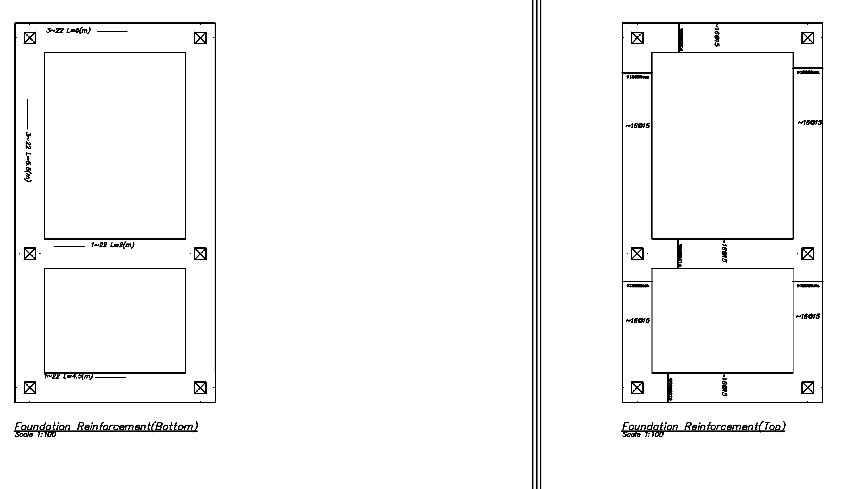
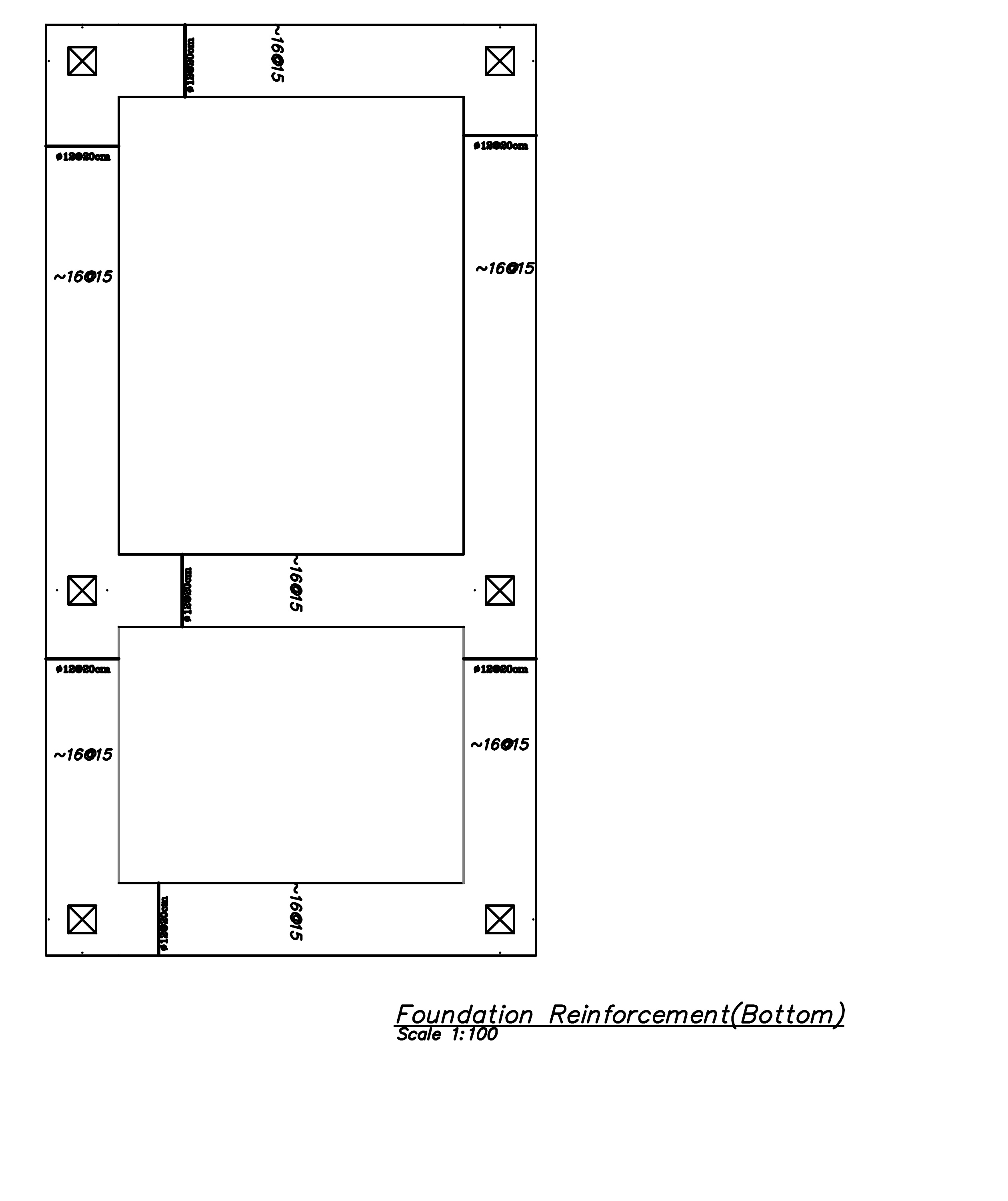
Foundation reinforcement in plan
This sheet presents the foundation reinforcement in bottom and top plan views. It records bar directions, selected bar quantities and lengths, and the relationship between the connected foundation strips and column positions. The paired views communicate the steel arrangement across the foundation footprint.
Top and bottom layouts · Longitudinal bars · Column locations
View drawing +
DRAWING 03 / st10.pdf
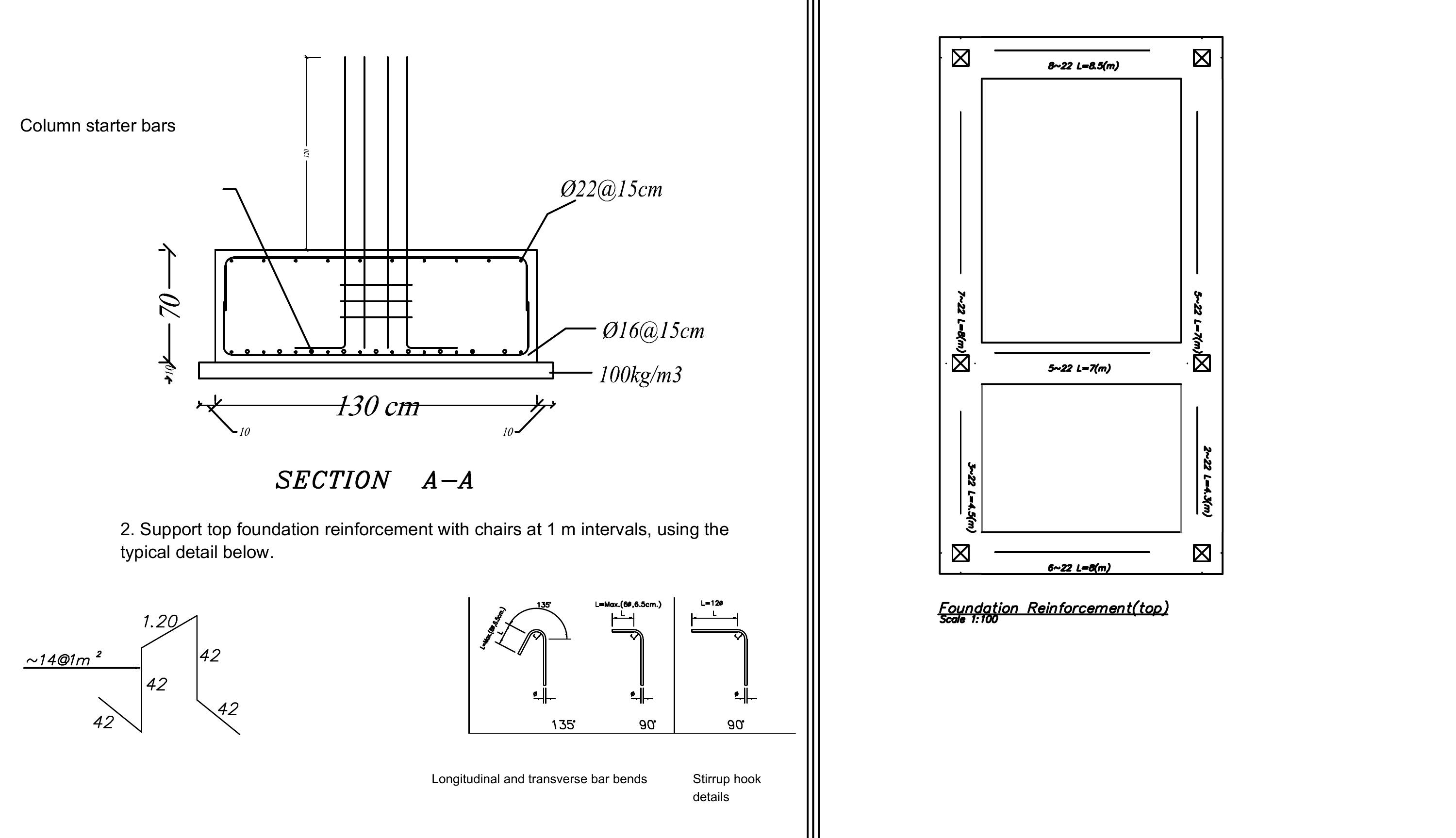
Foundation section, anchorage, and bar bends
Section A–A explains the foundation in depth: reinforcement layers, projecting column bars, and the concrete layer below the footing. The same sheet includes a reinforcement plan, chair detail, and bar-bending sketches. Together, these views connect the plan arrangement with the vertical placement and anchorage of the reinforcement.
Section A–A · Column starter bars · Chairs and bending details
View drawing +
DRAWING 04 / st13.pdf
Foundation bottom-reinforcement detail
The bottom-reinforcement plan provides a focused view of the foundation strips and the transverse bar callouts around the column positions. It complements the broader reinforcement plans by isolating the lower layer, making the intended reinforcement direction and spacing easier to follow.
Bottom layer · Transverse reinforcement · Strip intersections
View drawing +
03 / COLUMNS
Continuity through the storeys.
DRAWING 05 / st8.pdf
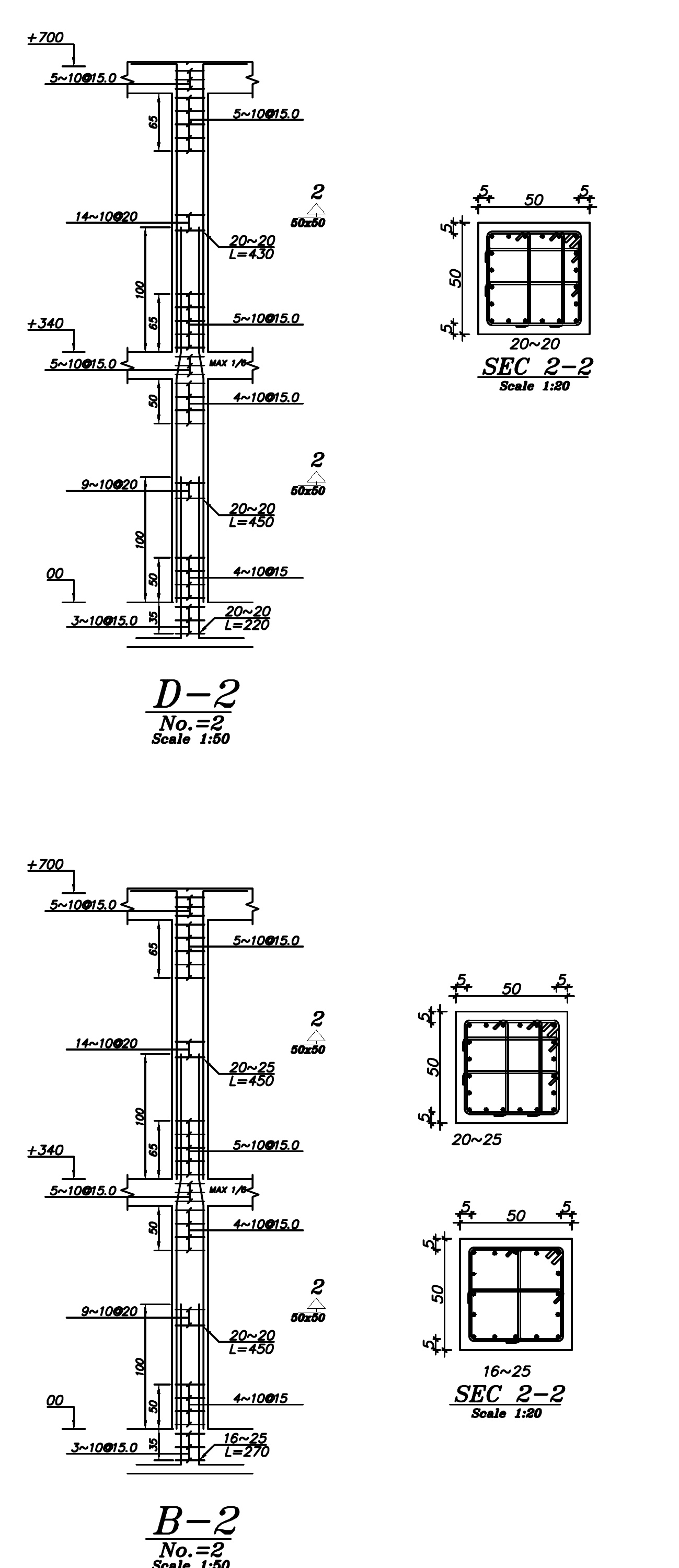
Columns at grid positions B-2 and D-2
The column elevations show reinforcement continuing between the marked floor levels, with longitudinal bar callouts and changes in tie spacing along the height. The accompanying sections show the arrangement of perimeter bars, ties, and internal cross-ties. Reading the elevation and sections together clarifies both vertical continuity and the reinforcement cage.
Storey-by-storey reinforcement · Tie zones · Cross-sections
View drawing +
DRAWING 06 / st7.pdf
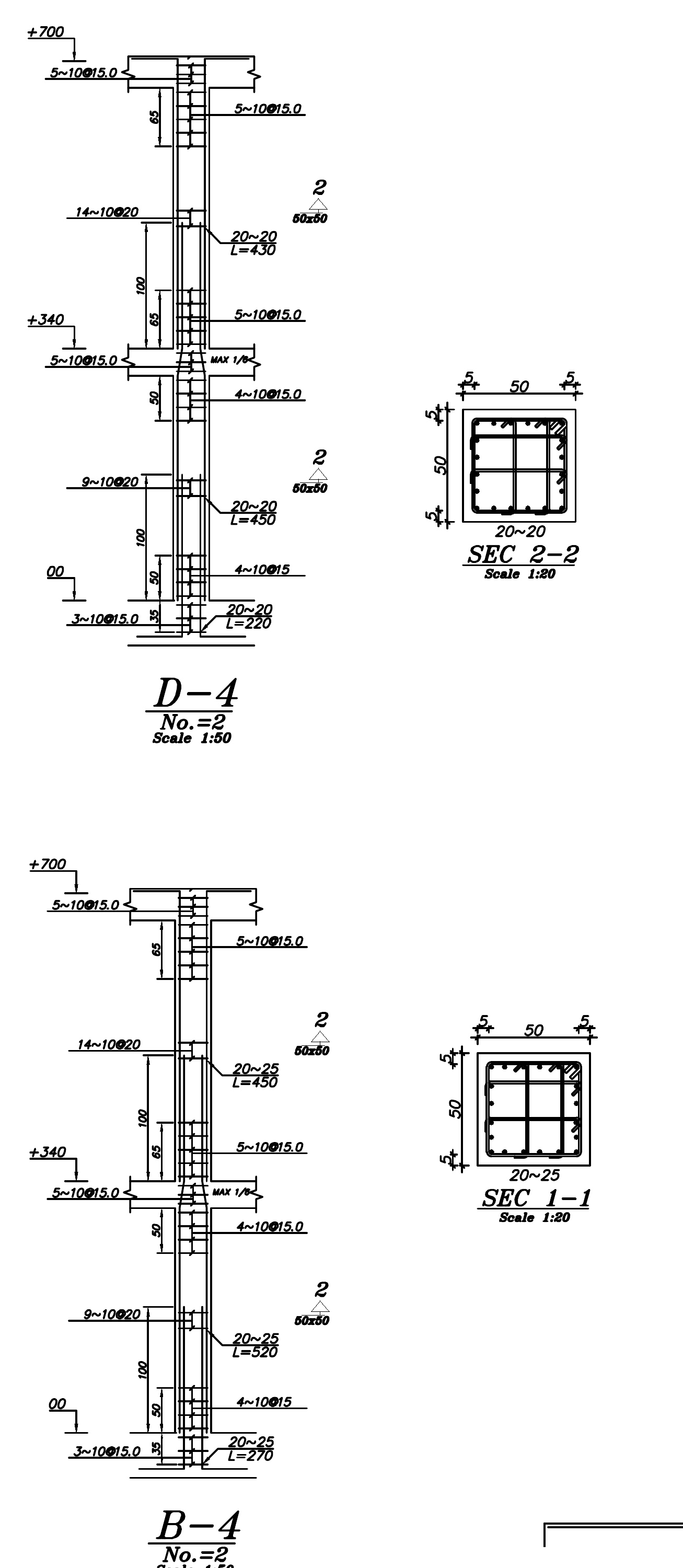
Columns at grid positions B-4 and D-4
These details document the B-4 and D-4 column reinforcement through both storeys. Bar lengths, reinforcement changes, and local tie zones are shown beside the elevations, while the sections define how the longitudinal bars are restrained across the column. The sheet also records the transition through the beam–column junctions.
Bar continuity · Beam–column junctions · Tie arrangements
View drawing +
DRAWING 07 / 2st6.pdf
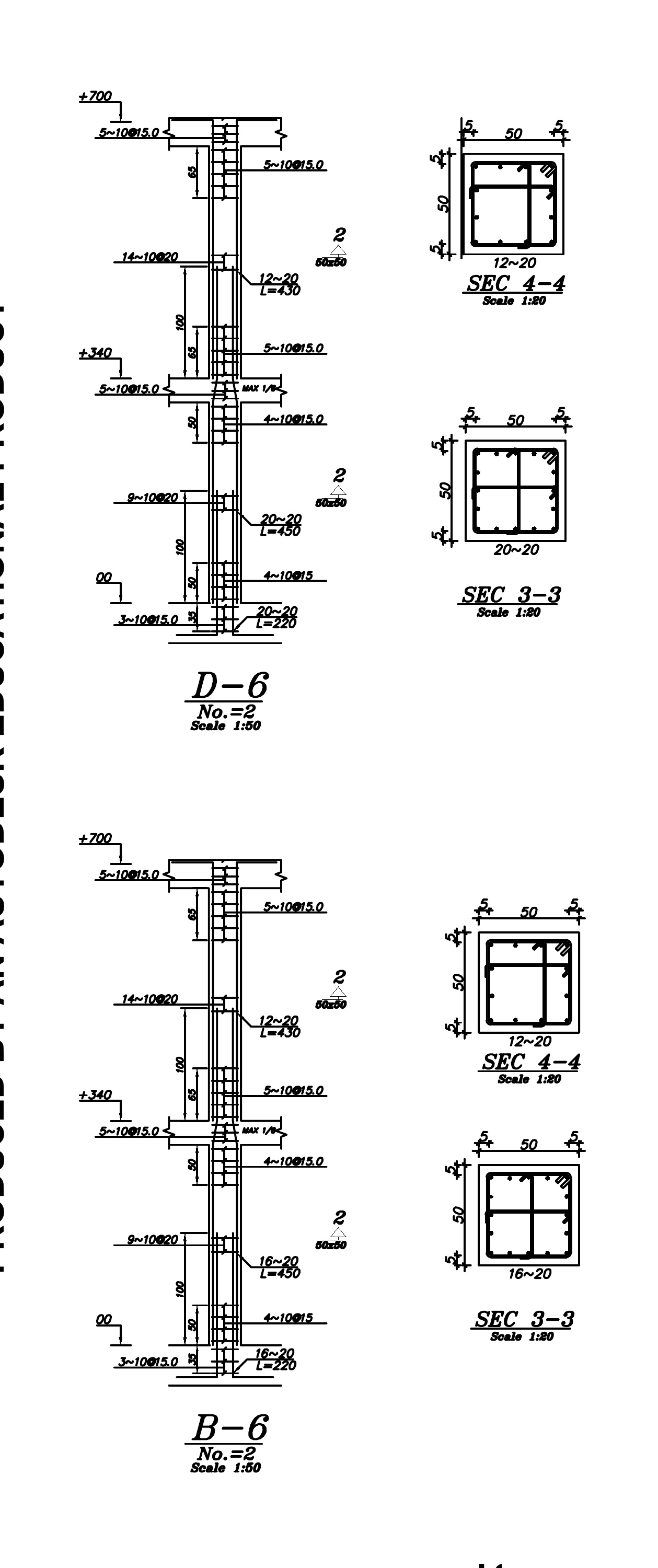
Columns at grid positions B-6 and D-6
The B-6 and D-6 elevations pair the vertical reinforcement with sections 3–3 and 4–4. The sections distinguish the reinforcement arrangements at different heights, and the elevation locates those changes relative to the floor levels. This keeps the column schedule tied to the actual position of each reinforcement cage.
Sections 3–3 and 4–4 · Reinforcement transitions · Floor levels
View drawing +
04 / BEAMS
The detail behind each frame line.
DRAWING 08 / 2st5.pdf
Beam type B-1
The first- and second-floor beam elevations combine support locations, end projections, longitudinal bars, and stirrup zones. The adjacent sections distinguish the reinforcement arrangement for each level. The detail shows how the same beam type is adapted across the two floors while maintaining a consistent drawing reference.
Floor-specific sections · End detailing · Stirrup zones
View drawing +
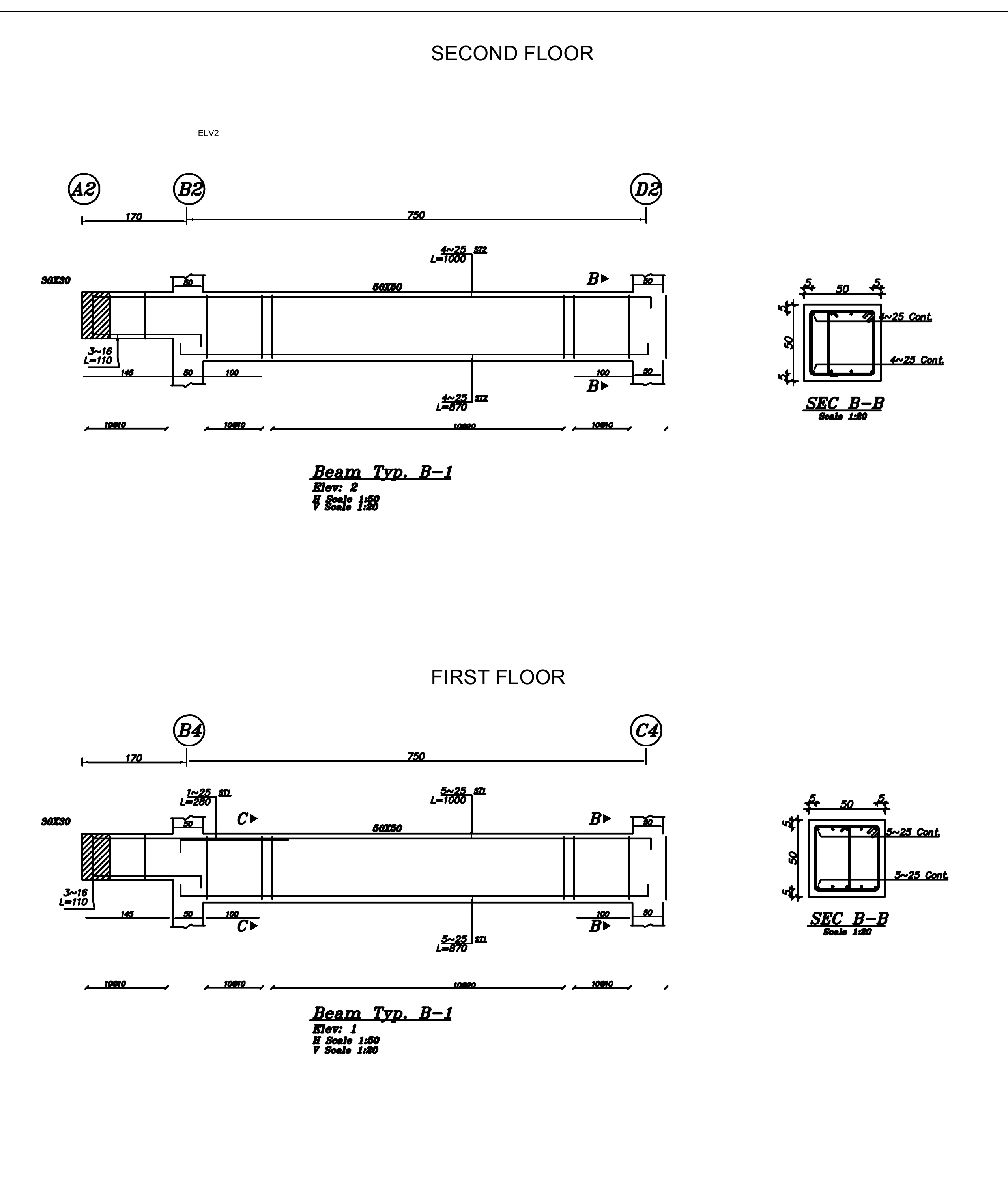
DRAWING 09 / 2st4.pdf
Beam type B-2
The B-2 sheet presents the beam in elevation and cross-section at both floor levels. Continuous top and bottom bars, anchorage at the ends, and changes in stirrup spacing are identified along the member. Comparing the two views makes the reinforcement differences between floors visible without losing the overall beam geometry.
Continuous bars · Anchorage · Elevation-to-section coordination
View drawing +
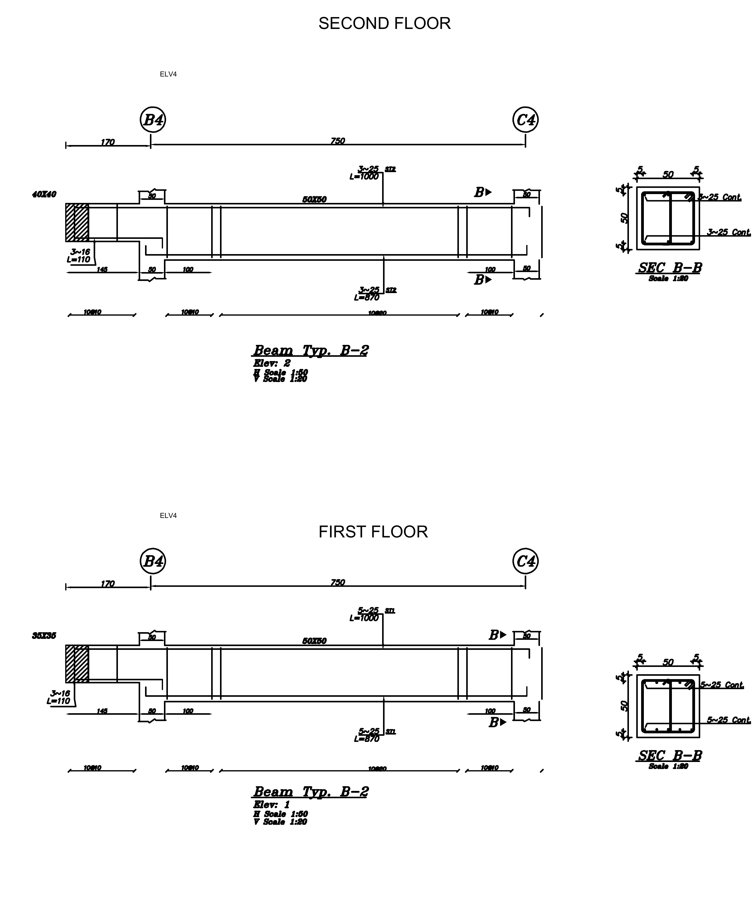
DRAWING 10 / 2st3.pdf
Beam type B-3
The B-3 details locate the beam against its support grid and show the reinforcement along the span and end projection. Cross-sections distinguish continuous bars from additional reinforcement, while the elevations identify the stirrup zones. This combines the member’s overall geometry with the local reinforcement needed to describe it for construction.
Support references · Continuous and additional bars · End projection
View drawing +
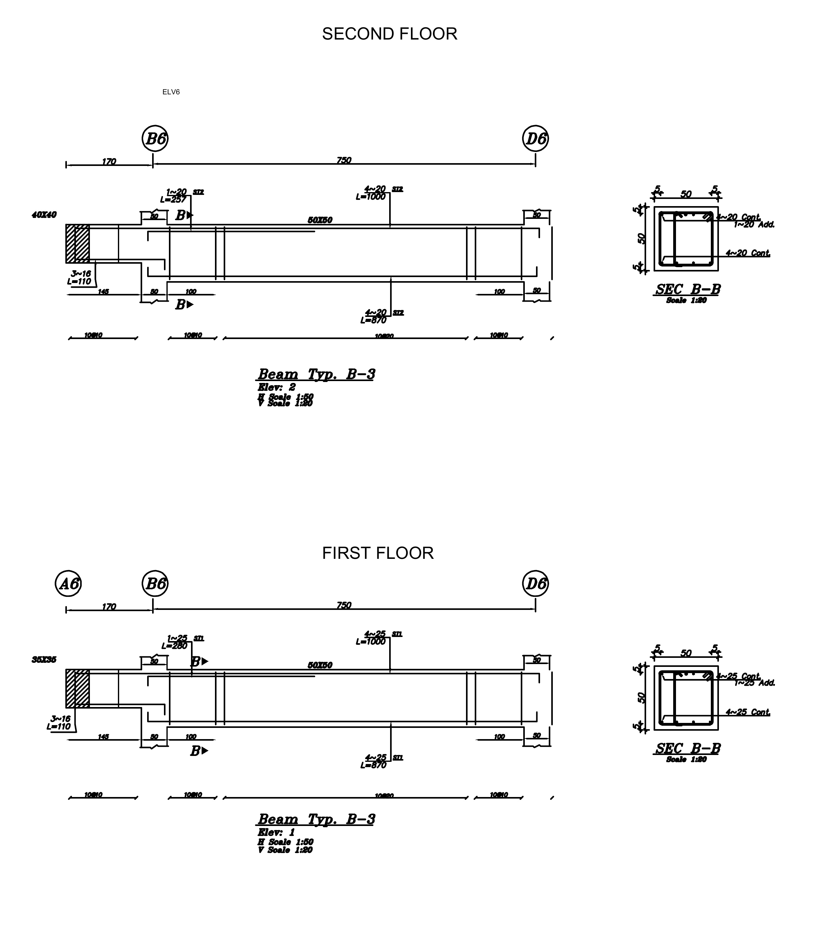
DRAWING 11 / 2st2.pdf
Beam type B-4 along grid B
This sheet follows the continuous B-4 beam along the B-grid column line at the first and second floors. The elevations show reinforcement through the intermediate support, bar extensions and cut-off locations, and stirrup-zone changes. The sections complete the detail by showing the top and bottom steel within the beam.
Multi-span continuity · Intermediate support · Bar extensions
View drawing +
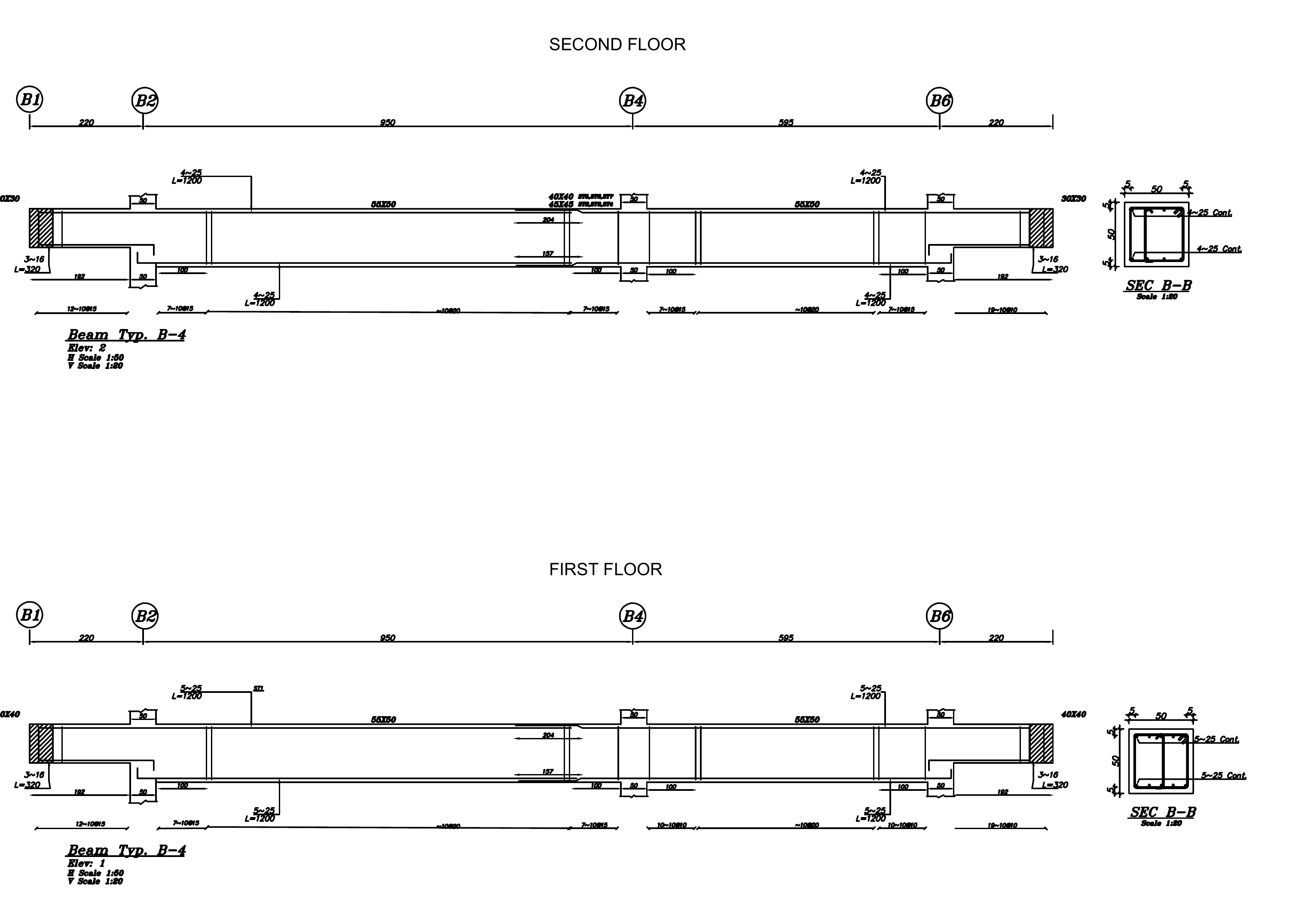
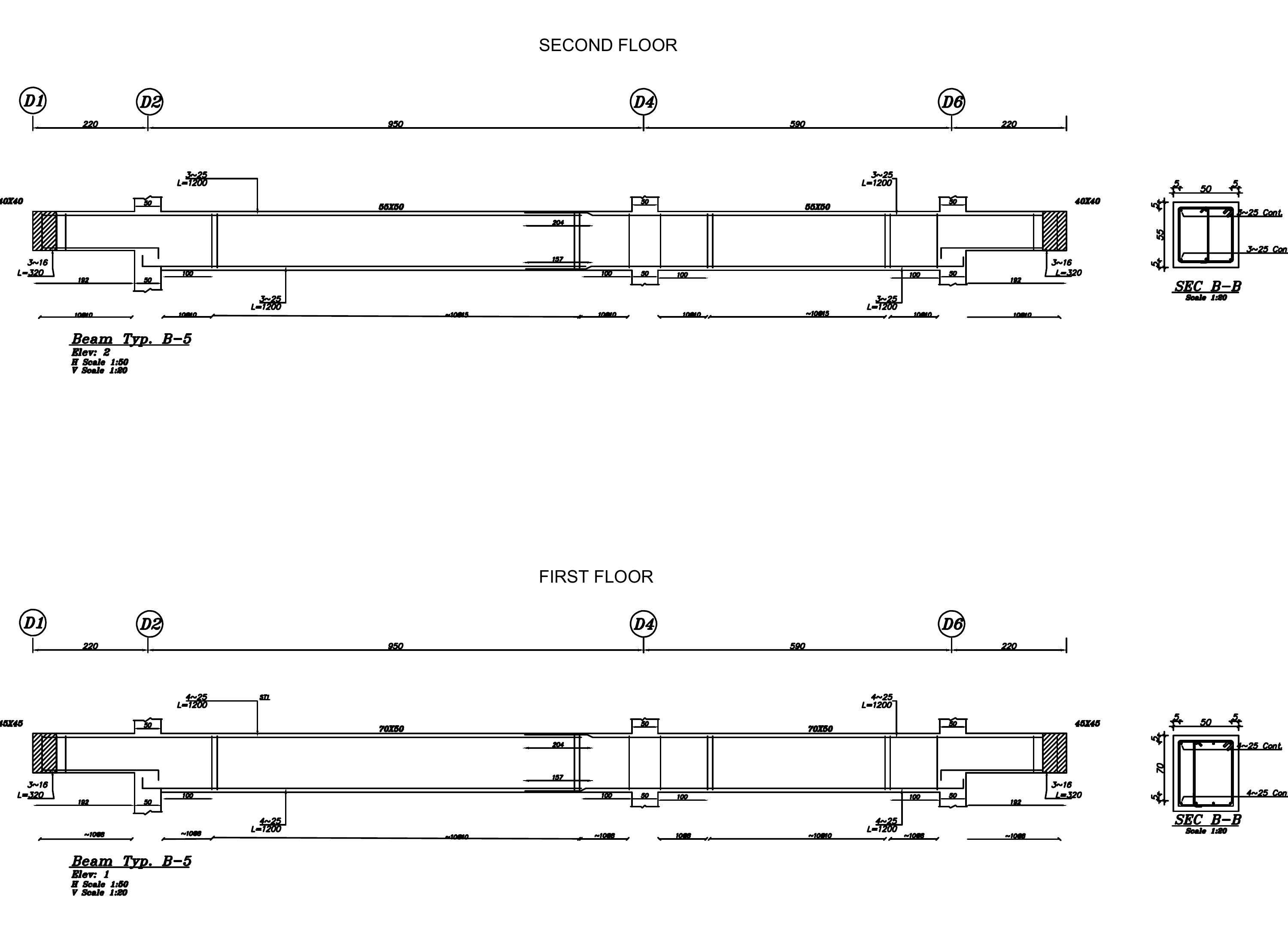
DRAWING 12 / 2st.pdf
Beam type B-5 along grid D
The B-5 elevations describe the continuous beam along the D-grid line, including its end projections and reinforcement across the intermediate support. Separate first- and second-floor details record the differing reinforcement arrangements. Bar lengths, extensions, stirrup zones, and sections turn the continuous frame line into a coordinated reinforcement detail.
Continuous frame line · Floor-by-floor reinforcement · Stirrups and sections
View drawing +
The connection between analysis and construction.
This project reflects the part of structural design I find especially valuable: turning a building scheme into clear information about reinforcement, continuity, anchorage, and member geometry. The plans locate the work; the elevations and sections explain how its parts fit together.

